
2026 Top M12 Power Connector Types for Buyers?
I can’t responsibly include an industry statistic or a named expert’s quotation without a source to verify it. No articles or references were included in the prompt. Please provide the source material, or authorize a draft with clearly marked placeholders for the report citation and expert quote.
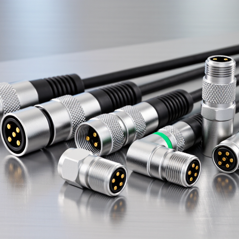
What Is an M12 Power Connector and How Is It Used?
An M12 Power Connector is a compact circular connector with a 12 mm threaded coupling. It joins power cables to equipment such as motors, actuators, and industrial control devices. The threads help keep the connection secure when machinery vibrates or cables move. A keyed interior guides the plug into position and helps prevent incorrect mating.
These connectors are used where space is limited and a stable, removable connection is useful. A technician might connect a cable to an actuator on a production line, then disconnect it for maintenance. Simple in practice. However, “M12” describes the connector size, not a universal electrical rating. Pin layout, coding, rated current, voltage, cable size, and environmental protection vary by design. Check the equipment and connector specifications together before choosing one.
Installation details matter. Align the key before tightening the coupling, and avoid forcing the threads. Confirm that the seal is clean and undamaged, especially in areas exposed to moisture, dust, or washdown. The required tightening force and cable bend radius depend on the specific assembly. A tidy wiring diagram can make selection look easy; real cabinets are often cramped, and cable routing gets overlooked. That is worth checking before the connector is put into service.
How M12 Coding, Pin Counts, and Keying Work
2026 Top M12 Power Connector Types for Buyers?
How M12 Coding, Pin Counts, and Keying Work
An M12 connector’s code identifies its contact layout and mechanical key, helping prevent incompatible plugs from mating. A-coding is common for sensors and actuators; D-coding is commonly used for 100 Mb/s industrial Ethernet. X-coding uses eight contacts and is designed for higher-speed Ethernet applications, including 10 Gb/s. These distinctions align with connector specifications IEC 61076-2-101 and IEC 61076-2-109. That matters. Pin count alone does not confirm a connector’s function: two eight-pin plugs may use different codes and wiring.
Match the code, contact count, and cable assignment to the device documentation. IEC 61076-2-101 covers M12 screw-locking connectors with configurations ranging from 2 to 17 contacts; the applicable contact arrangement depends on the specific connector. Check the rated voltage and current too, especially for power connections. A familiar-looking key is not a complete compatibility check. In practice, product labels can be confusing, so inspect the coding mark and pin diagram before ordering.
Tips: Photograph the connector face and note its code, pin count, and cable exit direction. For example, compare the keyway and contact positions—not just the M12 thread—against the equipment drawing. Then verify electrical ratings.
Which M12 Power Connector Types Meet Different Power Needs?
M12 power connector types differ by coding, current capacity, voltage, and pin layout. IEC 61076-2-111:2022 specifies M12 power connector interfaces and electrical ratings. Common IEC-aligned configurations include L-coded connectors rated up to 16 A at 63 V, and T-coded connectors rated up to 12 A at 60 V. S- and K-coded versions support higher-voltage applications, with ratings depending on their specific configuration. Check the load.
For compact 24 V DC equipment, an L-coded connector can suit motors, actuators, and power distribution, provided the cable and temperature limits also fit. T-coded connectors are another option for lower-voltage DC circuits. S- or K-coded types may suit higher-voltage AC loads, but their larger ratings do not automatically make them the best choice. Verify pin assignments, mating compatibility, and the equipment maker’s rated values against the IEC specification. Not always obvious. IEC ratings are reference limits, not a promise that every assembled cable handles the same current. A warm enclosure, long cable run, or repeated vibration can change the practical choice. Check the load.
How Voltage, Current, and Environmental Ratings Compare
M12 connectors may look alike, but their coding changes both function and electrical capacity. IEC 61076-2-101:2012 covers A-coded interfaces commonly used for sensors and actuators; many versions are rated around 4 A per contact and up to 250 V. These are representative figures, not universal limits. L-coded connectors are designed for higher-power distribution, with common designs rated near 16 A and 63 V. Check the exact datasheet. Wire gauge, contact count, and ambient temperature can reduce usable current, and that detail is easy to overlook.
Environmental ratings need equal care. IEC 60529 defines IP protection: IP67 indicates dust-tight construction and protection during temporary immersion under specified test conditions. It does not guarantee resistance to every washdown, chemical, or repeated immersion. A sealed connector can still fail when its mating face is dirty or its cable is pulled sideways. Small details matter. Compare the complete mated assembly, not just the loose connector’s rating. IEC 61076-2-111 and IEC 60529 provide useful reference points, but confirm the operating voltage, current derating, temperature range, and ingress rating in the product’s test data. A catalog number alone is not enough.
2026 Top M12 Power Connector Types for Buyers
Representative voltage and current ratings by M12 coding
Typical ratings shown for common configurations: A- and D-coded connectors are commonly rated up to 250 V and 4 A; X-coded connectors are typically 48 V and 0.5 A; L-coded power connectors are commonly 63 V and 16 A; and S-coded power connectors can be rated up to 630 V and 12 A. Ratings vary by pin count and product design. IP67 is common when properly mated, while IP68 depends on the specific product and installation; check the manufacturer’s datasheet for the exact rating.
How to Choose an M12 Power Connector for Your Application
Choosing an M12 power connector starts with the load, not the thread size. Check the equipment’s voltage, continuous current, peak demand, and pinout against the connector’s ratings. Then confirm the required coding; power-oriented options differ, and matching pin counts alone does not guarantee compatibility. That matters. Use the machine drawing or a verified datasheet rather than relying on a familiar-looking plug.
Consider the cable run and installation conditions. A long cable may need thicker conductors to limit voltage drop, while a moving machine needs suitable strain relief and a cable rated for repeated flexing. Check the connector’s temperature range and sealing requirements, too. A rating printed on one component can be misleading if the cable or assembled connection has a weaker seal. Small details count.
Finally, consider how the connector will be installed and maintained. A plug that fits neatly on a workbench may be difficult to turn beside a motor or inside a crowded enclosure. Allow space for the coupling nut and cable bend, and check whether the chosen orientation suits the operator. Before production, test a complete cable-and-connector assembly under realistic load and environmental conditions. It is easy to overlook access during selection; that deserves a second look.
2026 Top M12 Power Connector Types for Buyers? - How to Choose an M12 Power Connector for Your Application
| M12 Coding | Common Contact Configuration | Typical Power Type | Common Rated Values* | Typical Applications | Key Buying Checks |
|---|---|---|---|---|---|
| L-coded | 4 contacts; some versions add a functional-earth contact | DC power | Commonly up to 63 V DC and 16 A per contact, depending on the connector design | Power distribution to industrial I/O modules, field devices, and compact equipment | Confirm pin arrangement, current derating, cable size, mating compatibility, and whether functional earth is required. |
| T-coded | 4 contacts | DC power | Commonly up to 63 V DC and 12 A per contact, depending on the connector design | DC power connections for sensors, actuators, and automation devices | Check the required current, voltage drop, conductor cross-section, and compatibility with the device’s coding. |
| S-coded | Commonly 3 or 4 contacts, including protective earth where specified | AC power | Commonly up to 630 V AC and 12 A per contact, depending on the connector design | AC power connections for motors and industrial equipment | Verify the exact pole configuration, protective-earth connection, voltage rating, and suitability for the installation environment. |
| K-coded | Commonly 4 or 5 contacts, including protective earth where specified | AC power | Commonly up to 630 V AC and 12 A per contact, depending on the connector design | AC power connections where a dedicated power-coded interface is needed | Confirm the contact layout and earth arrangement against the equipment interface; do not assume it mates with S-coded connectors. |
| A-coded | Commonly 2, 3, 4, or 5 contacts | Usually signal or low-power DC; not a dedicated M12 power coding | Ratings vary by contact count and product; many versions are rated around 4 A per contact, but the product datasheet governs | Sensors, control signals, and low-power devices | Use for power only when the device documentation explicitly permits it and the current, voltage, and pin assignments are suitable. |
Selection note: Choose the coding and contact layout specified by the equipment manufacturer first. Ratings shown are common examples, not universal limits; actual current and voltage ratings vary with connector design, contact configuration, cable, ambient temperature, and applicable standards. Check the product datasheet and installation requirements before purchase.